
LED light strips can make a great accent to your desk, TV, kitchen or elsewhere in your home. Wouldn’t it be great to build one that can be controlled over WiFi? How about making cool animations that go with a holiday, sports team or time of day. Today, I’m giving my implementation of a WiFi Connected RGB LED Strip that you can use to add some lights and fun to your home.
Hardware
I’m going to go over some basics of LED strips and go over how I went about creating mine. There are plenty of tradeoffs when choosing an LED strip including LED density, power consumption, addressability and weather durability. I’m going to touch briefly on those and discuss the LED strip I’m using in this project.
LED Strip
First off, you need to decide if you want to be able to change the color of each LED on the strip individually (digital) or you are okay with the whole strip being the same color (analog). If you want to do “cool” animations or interesting designs usually a digital LED strip is the way to go. If you are just adding some accent coloring underneath your kitchen cabinet, an analog LED strip might be the right choice for you. For this article, I’ll be focusing on a digital LED strip but some of the same concepts will still apply. Digital LED strips are often called “addressable” because you can address each LED individually on the strip. Sometimes the LEDs are actually grouped together in groups of 3, so you address by the group.
Next, you’ll need to consider LED density. This just refers to how many leds are on your strip per meter. The denser the strip the better the color transitions will look, but that comes at a cost. Also, the more LEDs per meter requires more power!
Another thing to consider is the durability of the LEDs. The requirements will be different if you are placing them outside uncovered in the rain versus inside behind a TV. When researching LED strips the IP value will tell you the durability. The first digit of the IP value indicates the dust rating and the second digit indicates the water rating. For a full breakdown of what the values mean check out this resource.
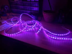
The main LED strip I use is this 12V strip with 60 LEDs/meter and IP65 rating and the WS2811 controller. Definitely look around for deals though and determine what makes sense for your project.
Connectivity
There are several ways to connect your LED strip to your Home Automation system. Today, I’m going to be using a NodeMCU which will connect over WiFi to my MQTT broker. Home Assistant will also connect to the MQTT broker and will allow me to program automations for the lights as well as manually control them. Check out my article on Setting up an MQTT broker if you are not already using MQTT for any Home Automation.
Power
Once you pick out your LED strip, you need to figure out how to plan for power. These LEDs can definitely draw a decent amount of power and you’ll need to plan accordingly. Most LED strips I’ve seen run at 12V or 5V so pay attention when you are reviewing strips. The seller should also list how much current (in Amps) or Power (in Watts) is needed for the strip. Remember that Power = Current * Voltage. Looking at the listing for the strip I posted above the seller says the strip uses 72 Watts at 12 Volts. So we can determine we need a power supply that runs at 12V and can supply 6 Amps of current because 72W / 12V = 6A.
Of course, if you are planning on stringing together multiple LED strips together, you’ll need to provide more current for the additional strips. So if you’re planning on using 5 of these strips at once all connected together, you’ll need a 12V supply that can provide 30 A. In that scenario, it’s best to connect each strip to the power supply directly to reduce voltage drop. You’ll know that you’re experiencing voltage drop if the LEDs at the end of the strip aren’t as bright as the ones near the power supply.
You might have an old laptop charger like this that meets the specs. Or if you’re using multiple strips a beefier power supply like this one might be needed.
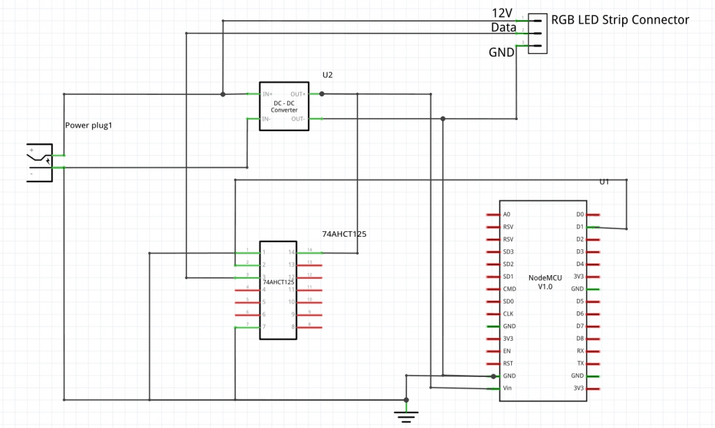
Finally, you’ll need to power your Microcontroller. You could plug the NodeMCU into the wall, but that’s kind of awkward. Why should you have to plug two things in? You can get a DC/DC converter to step down the 12V from the power supply to 5V for the NodeMCU. That way you only have to plug in one thing. Finally, because the LED strip is running at 12V and the NodeMCU is running with 3.3V GPIO Pins you need a logic level shifter to correctly shift the data lines to the voltage needed by the LED strip.
UPDATE (Oct 18, 2018)
After some experimentation and more research, I changed logic level converter used in the design. I now recommend the 74AHCT125 that Adafruit sells. This level converter works much faster and can keep up with the speed of data for the WS2811 LED strips. I found a great article here explaining the difference of several logic level converters. I’ve updated the schematic and parts list below.
Summary
So hopefully you’re not scared off from making your DIY WiFi Connected LED strip yet. While it there is a lot of different parts they all work together to make a really flexible system. Here’s a breakdown of all the parts listed in this section.
| Item | Comments |
|---|---|
| LED Strip | The LED Strip! |
| Power Supply (72W) | LED Power Supply - 72W |
| LED Power Supply (360W) | LED Power Supply - 360W |
| DC/DC Converter 12V to 5V | DC/DC Converter to power NodeMCU from LED Power Supply |
| NodeMCU | The WiFi programmable microcontroller we can use to control the lights |
| Logic Level Converter | Logic Level Converter to convert the 3.3V data signal coming out of the NodeMCU to 5V for the LED strip |
| LED Connector Cable | Nice cables for connecting LED strips |
| LED Channel Diffuser | Can be useful to diffuse LED lights |
| Power Jacks | Power Jack to connect power supply to protoboard |
| Protoboard | Protoboard for mounting electronics |
| Plastic Boxes | Plastic box to mount electronics. Could also 3D print this. |
Reference the below schematic on how to wire up the strip to your microcontroller. The power coming from the power supply is routed through the DC/DC converter to power the NodeMCU as well as routed to the LED strip connector and the logic level converter. The NodeMCU sends its data signal through the logic level converter before reaching the LED connector. Feel free to leave me comments and/or questions in the comments!
Software
Now let’s get to the software! My implementation allows you to set a color to fill the strip with a single color, change the brightness or choose an effect. Using Home Assistant all those things can be done automatically as well so you can have the LEDs turn on at certain times of the day or any other activity. Want to set it to your team’s colors on game day? Or show a candy cane effect during Christmas? All that can be automated in Home Assistant. This code also supports Over the Air updates so you can upload a new version of the software without having to plug in the USB connection. Learn more about Over the Air updates in my article 4 Essential Tips for Improving Your DIY Home Automation Project.
Embedded
All of my software is available in my GitHub repository for this project. Rename the src/config_template.h to be src/config.h and edit the values for your system. My software uses the Arduino framework for the NodeMCU but I use PlatformIO for doing the build process and managing libraries. Check out the PlatformIO installation page to see how you can install it.
I’m not going to go through all the code in the project but wanted to point out a few high-level things on how it works.
To set the stage, every iteration of the loop() function is essentially a “frame” for an effect. The software uses the FastLED library and essentially there is a global array holding the color of each LED. The main loop logic updates this array once per iteration of the loop and then sends the data to the LED strip.
MQTT Callback
MQTT messages dictate the requested color of the LEDs on the strip. The main loop is responsible for processing those messages and setting up the LED array. Whenever new data comes on an MQTT topic the below MQTT callback function is called process the payload.
|
1 2 3 4 5 6 7 8 9 10 11 12 13 14 15 16 17 18 19 20 21 22 23 24 25 26 27 28 29 30 31 32 33 34 35 36 37 38 39 40 41 42 43 44 45 46 47 48 49 50 51 52 53 54 55 56 57 58 59 60 61 62 63 64 65 66 67 68 |
void callback(char *topic, byte *payload, unsigned int length) { char payloadString[20]; char colorStrings[3][4]; Serial.print("Message arrived ["); Serial.print(topic); Serial.print("] "); memcpy(payloadString, payload, length); payloadString[length] = '\0'; Serial.println(payloadString); // Process the command that was received if (strcmp(topic, COMMAND_TOPIC) == 0) { Serial.println("Processing the command..."); if (strncmp(payloadString, "on", length) == 0) { TurnOn = true; } else { TurnOff = true; } } else if (strcmp(topic, BRIGHTNESS_COMMAND_TOPIC) == 0) { Serial.println("Processing the brightness..."); UpdateBrightness = true; Brightness = atoi(payloadString); } else if (strcmp(topic, RGB_COMMAND_TOPIC) == 0) { Serial.println("Processing the RGB..."); UpdateColorFill = true; unsigned int component = 0; unsigned int j = 0; for (unsigned int i = 0; i < length; i++) { if (payload[i] == ',') { colorStrings[component][j] = '\0'; component++; j = 0; } else { colorStrings[component][j] = payload[i]; j++; } } colorStrings[component][j] = '\0'; Red = atoi(colorStrings[0]); Green = atoi(colorStrings[1]); Blue = atoi(colorStrings[2]); } else if (strcmp(topic, EFFECT_COMMAND_TOPIC) == 0) { Serial.println("Processing the Effect..."); UpdateEffect = true; if (strcmp(payloadString, "rainbow") == 0) { CurrentEffect = RAINBOW; } else if (strcmp(payloadString, "rainbow_with_glitter") == 0) { CurrentEffect = RAINBOW_WITH_GLITTER; } else if (strcmp(payloadString, "confetti") == 0) { CurrentEffect = CONFETTI; } else if (strcmp(payloadString, "sinelon") == 0) { CurrentEffect = SINELON; } else if (strcmp(payloadString, "bpm") == 0) { CurrentEffect = BPM; } else if (strcmp(payloadString, "juggle") == 0) { CurrentEffect = JUGGLE; } else if (strcmp(payloadString, "candycane") == 0) { CurrentEffect = CANDYCANE; } } } |
- We start off with some basic debug statements to help when debugging the device. This lets us easily see what message we’re processing.
- Next, we convert the payload data to a proper string in order to easily compare it
- Then, the topic is compared to all the topics that we are subscribed to. Processing the payload is different for each topic.
- A set of global variables tells the main loop what needs to happen (
TurnOn,TurnOff,UpdateBrightness,UpdateColorFill, andUpdateEffect.) One of these is set totruedepending on the topic. - Finally, the payload is parsed based on the kind of data expected.
Main Loop
The main loop is responsible for reading the global variables set by the callback and deciding how to color the LED strip. Every iteration of the loop updates the LED coloring once. This is just a snippet of the loop so be sure to check the GitHub repository.
|
1 2 3 4 5 6 7 8 9 10 11 12 13 14 15 16 17 18 19 20 21 22 23 24 25 26 27 28 29 30 31 32 33 34 35 36 37 38 39 40 41 42 |
// Process MQTT tasks client.loop(); if (TurnOn) { TurnOn = false; showLeds = true; FastLED.setBrightness(Brightness); client.publish(STATE_TOPIC, "on"); client.publish(BRIGHTNESS_STATE_TOPIC, String(Brightness).c_str()); } if (TurnOff) { TurnOff = false; showLeds = false; FastLED.setBrightness(0); client.publish(STATE_TOPIC, "off"); client.publish(BRIGHTNESS_STATE_TOPIC, String(0).c_str()); } if (UpdateBrightness) { UpdateBrightness = false; FastLED.setBrightness(Brightness); client.publish(BRIGHTNESS_STATE_TOPIC, String(Brightness).c_str()); } if (UpdateColorFill) { UpdateColorFill = false; runEffect = false; Serial.println(rgbString()); fill_solid(&(leds[0]), NUM_LEDS, CRGB(Red, Green, Blue)); client.publish(RGB_STATE_TOPIC, rgbString().c_str()); client.publish(EFFECT_STATE_TOPIC, String("").c_str()); } if (UpdateEffect) { UpdateEffect = false; runEffect = true; client.publish(EFFECT_STATE_TOPIC, String(EffectStrings[CurrentEffect]).c_str()); client.publish(RGB_STATE_TOPIC, String("").c_str()); } // Fill the LED array with an effect if an effect is active if (runEffect) { EffectFxns[CurrentEffect](); } |
- First off, process any MQTT messages we need to act on
- Next check if the strip needs to be turned off or on. To turn off we can set the brightness to 0 temporarily.
- The FastLED library has a nice function called
fill_solidthat allows us to fill the strip a solid color - If an effect was chosen, we set the local variable
runEffecttotrue.This uses a table of functions to look up the right function to call for filling in the LEDs. - Adding new effects is easy, you just need to create a new function for your effect and add it to the
EffectFxnsarray along with adding some processing to decode the MQTT message.
Home Assistant
Home Assistant comes with an MQTT RGB Light component that we can use. This essentially defines what features the light supports and what MQTT topics to post the commands to and receive status updates. These should be matching whatever you put in your config.h file. When you add new effects, this list will need to be updated as well for the UI to work. The following YAML will work my ESP8266 software:
|
1 2 3 4 5 6 7 8 9 10 11 12 13 14 15 16 17 18 19 20 21 22 23 24 |
--- - platform: mqtt name: "Office Light RGB" state_topic: "office/rgb1/light/status" command_topic: "office/rgb1/light/switch" brightness_state_topic: "office/rgb1/brightness/status" brightness_command_topic: "office/rgb1/brightness/set" rgb_state_topic: "office/rgb1/rgb/status" rgb_command_topic: "office/rgb1/rgb/set" effect_state_topic: "office/rgb1/effect/status" effect_command_topic: "office/rgb1/effect/set" effect_list: - rainbow - rainbow_with_glitter - confetti - sinelon - bpm - juggle - candycane qos: 0 payload_on: "on" payload_off: "off" optimistic: false |
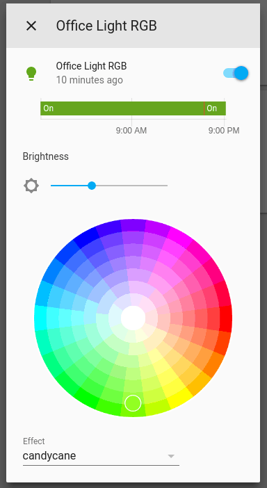
After restarting Home Assistant you should be able to access the light through the UI. It allows you to change the color, brightness, and effect.
Next Steps
If you’ve followed along you should have an awesome RGB LED strip that you can control over WiFi using Home Assistant. In a future article, I’ll be going into more details on how you can make effects and set up automations. Let me know of any cool LED projects you’ve done in the comments!