

My wife and I use the garage every day to go in and out our house. Wouldn’t you like to automatically make sure your garage door is closed at night? Or know the status of it when you’re away from the house? Today I’m going to use some inexpensive electronics to turn your standard garage door into a “smart” garage door. This design still keeps all the original functionality of your garage door intact, you won’t have to use an app or website to open the garage door, it just brings the garage door into the digital world.
For this project, we’re going to hook up an ESP8266 to our garage door opener to control over Home Assistant using MQTT. Some hardware you’ll need for this project:
From a software perspective, you’re going to need Home Assistant running with an MQTT broker and an ESP8266 running MicroPython. Check out these blog posts for setting those up:
Hardware
For this project, we’re using a NodeMCU as the main microcontroller which connects to WiFi and interacts with an MQTT broker. The NodeMCU uses a simple magnetic reed switch to determine when the garage door is open/closed. You can see in the schematic below the reed switch (S1) is connected between D1 on the NodeMCU and GND.
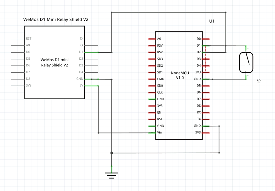
When the door is open, the magnets will be far apart, so reading from the D1 pin the switch will be open and the voltage will be floating. We can use the internal pull up resistor of the NodeMCU to pull that floating voltage high. When the door is closed the magnets will be touching, and we’ll get a GND connection going through the switch, so reading from D1 will show 0V.
The next piece of hardware is the relay. We can use a relay to operate as a switch pressing the garage door opener for us controlled by the Node MCU. Referring back to the schematic, pin D2 on the NodeMCU can control if the relay is active or not. When the relay is hooked up to your garage door opener, activating the relay for a short time will trigger the door opening and closing, essentially like pressing your garage door opener button.
Software
For this project, I decided to use MicroPython for writing the firmware for the device. Using MQTT, the device can update the status of the garage door (opened/closed) and also remotely open and close the garage door.
We need a few MQTT topics to interact with the device. In Home Assistant, I created a new MQTT cover with the following settings:
|
1 2 3 4 5 6 7 8 9 10 11 12 13 14 15 16 |
--- - platform: mqtt name: "Garage Door" state_topic: "home/garage/garagedoor" command_topic: "home/garage/garagedoor/set" availability_topic: "home/garage/garagedoor/available" payload_open: "open" payload_close: "open" payload_stop: "open" state_open: "open" state_closed: "closed" payload_available: "online" payload_not_available: "offline" optimistic: false retain: false |
The NodeMCU publishes the current status of the door to home/garage/garagedoor. It subscribes to the home/garage/garagedoor/set topic to listen for new commands from Home Assistant to open or close the door. Finally, I included an availability topic at home/garage/garagedoor/available to show if the controller is up and running.
MicroPython Firmware
All of the code for the firmware is available in my git repository on GitHub. A lot of the code is very similar to my article on Creating a DIY Home Assistant Switch using MicroPython so refer to that too to get a better understanding of the code. Change the variables in config.py to adapt for your WiFi network.
To start off, Micropython always runs boot.py, in this application we are not doing anything too interesting, just connecting to the WiFi and printing out the IP address once we’re connected.
|
1 2 3 4 5 6 7 8 9 10 11 12 13 14 15 16 17 18 19 20 |
import gc import network from config import ESSID, PASSWORD gc.collect() print("Starting...") def connect(): sta_if = network.WLAN(network.STA_IF) if not sta_if.isconnected(): print('Connecting to network...') sta_if.active(True) sta_if.connect(ESSID, PASSWORD) while not sta_if.isconnected(): pass print('Network config:', sta_if.ifconfig()) connect() |
Application Startup and Configuration
Once the bootup completes, MicroPython runs the main.py script. I’m going to be breaking down the software in chunks. The first part of the main() function sets up the application.
|
1 2 3 4 5 6 7 8 9 10 11 12 13 14 15 16 17 18 19 20 21 22 23 24 25 26 27 28 29 |
def main(): global relay_pin client = MQTTClient(CLIENT_ID, SERVER) client.set_callback(new_msg) try: client.connect() except OSError: print("MQTT Broker seems down") print("Resetting after 20 seconds") time.sleep(20) machine.reset() client.subscribe(COMMAND_TOPIC) # Publish as available once connected client.publish(AVAILABILITY_TOPIC, "online", retain=True) switch_pin = machine.Pin(5, machine.Pin.IN, machine.Pin.PULL_UP) reed_switch = Switch(switch_pin) # Initialize state of garage door after booting up if switch_pin.value(): client.publish(STATE_TOPIC, "open", retain=True) else: client.publish(STATE_TOPIC, "closed", retain=True) relay_pin = machine.Pin(4, machine.Pin.OUT, 0) |
- Creates an MQTT client and sets a callback function whenever a message appears on the topics our device is interested in
- Tries to connect to the MQTT broker, if the broker appears down it resets the device after 20 seconds. This will trigger running
boot.pyagain - Subscribes to the command topic to activate after recieving a command from Home Assistant
- Publishes a message to the availability topic to let all subscribers (like Home Assistant) know it is now online.
- Initializes the reed switch as a GPIO on pin 5. Uses my custom
Switchclass for software debouncing of a switch (more on that in another article). The pin is initialized with a Pull Up resistor so that when the circuit is open it reads as a “1”. - Checks the current value of the switch pin to initialize the state topic correctly
- Initializes the relay pin as a GPIO on pin 4.
The main() loop
Okay so now the device is initialized and ready to interact with the world. The next part of the application is the main loop of the application.
|
1 2 3 4 5 6 7 8 9 10 11 12 13 14 15 16 17 18 19 20 21 22 23 24 25 26 27 28 |
try: while True: reed_switch_new_value = False # Disable interrupts for a short time to read shared variable irq_state = machine.disable_irq() if reed_switch.new_value_available: reed_switch_value = reed_switch.value reed_switch_new_value = True reed_switch.new_value_available = False machine.enable_irq(irq_state) # If the reed switch had a new value, publish the new state if reed_switch_new_value: if reed_switch_value: client.publish(STATE_TOPIC, "open") else: client.publish(STATE_TOPIC, "closed") # Process any MQTT messages if client.check_msg(): client.wait_msg() finally: client.publish(AVAILABILITY_TOPIC, "offline", retain=False) client.disconnect() machine.reset() |
- The loop runs in a
while Trueloop because it never needs to exit - The local variable
reed_switch_new_valueis used at the application level to keep track if a new value needs to be published to the state topic. - To read from shared variables it’s usually best to disable interrupts before reading, but you want to execute as little code as possible when the device has interrupts disabled. While interrupts are disabled the code checks the reed switch for a new value and conditionally resets the variables. Because the Switch class also modifies these variables it’s best to do this while interrupts are disabled to make sure no other threads are modifying these variables at the same time.
- If there is a new value available, the device publishes on the state topic
- We then process any MQTT messages if there are any.
- The whole main loop is in a try/finally block so that if anything goes wrong and an exception is raised the device publishes an offline message and resets.
Finally, we can look at the callback function for when a message is published to the command topic. This callback function just prints out some debug information to the screen and turns the relay pin on for 600 ms. That’s enough time for the contacts to be shorted and start activating the garage door opener.
|
1 2 3 4 5 6 7 |
def new_msg(topic, msg): print("Received {} on {} topic".format(msg, topic)) print("Turning relay on") relay_pin.value(1) time.sleep_ms(600) print("Turning relay off") relay_pin.value(0) |
In summary, the code basically monitors the reed switch to determine the current state of the door and publishes that to the state topic. At the same time, it waits for messages on the command topic and starts the garage door opener when it receives a new message.
Home Assistant
Home Assistant has a great component for this, the MQTT Cover. The MQTT Cover component allows you to control any “cover” which includes blinds, roller shutter or garage door. To add the new MQTT cover you can add the following to your configuration.
|
1 2 3 4 5 6 7 8 9 10 11 12 13 14 15 |
cover: - platform: mqtt name: "Garage Door" state_topic: "home/garage/garagedoor" command_topic: "home/garage/garagedoor/set" availability_topic: "home/garage/garagedoor/available" payload_open: "open" payload_close: "open" payload_stop: "open" state_open: "open" state_closed: "closed" payload_available: "online" payload_not_available: "offline" optimistic: false retain: false |
This defines all the topics and payloads to match up with our firmware. I also found it useful to use the following customization to make the icons on the Home Assistant front end look more like a garage door.
|
1 2 |
cover.garage_door: device_class: garage |
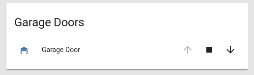
This results in a new card in Home Assistant showing the status of the garage door and buttons to open/close/stop it.
Prototyping to Production
Sometimes writing the software proves easier than actually hooking the device up. Some things I used to make the device a little more permanent in my garage:
| Item | Comments |
|---|---|
| Protoboard | Used to solder down the ESP8266 and Relay board |
| Standoffs | Standoffs to attach the protoboard to the case |
| Project Boxes | Box to enclose everything in. Could use a 3D printer if you have one instead. |
| Wire Terminals | Terminals to create good connection to screws on garage door. |
| Header Pins | Header pins for connecting magnetic sensor to protobard |
| Wire | Wire for magnetic sensors to protoboard |
Most of these will last you a few projects so you might already have them laying around or just think of it as an investment for future projects!
Prototyping
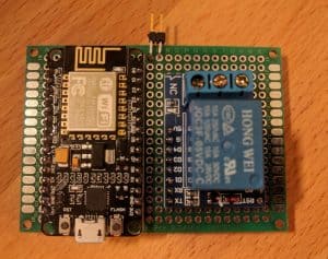
After flashing the software onto the NodeMCU and updating the Home Assistant configuration you can test out the configuration by triggering the device through Home Assistant. Here’s a little demo of my setup on a breadboard while developing the software. The relay turns on (you can tell by the red LED) when activating in Home Assistant. Moving the magnet to and from the switch changes the status in Home Assistant.
Moving to Production
Now that we’re done prototyping it’s time to move to the final location. First, you need to determine which terminals on your garage door opener activate the garage door, on mine it’s the two leftmost terminals. Try connecting a piece of wire between two terminals to see what triggers the door.

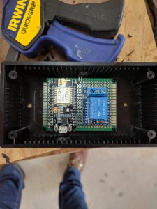
I then ended up soldering my devices onto a protoboard so they stay in place better. I used a right angle male header to create a connection point for the relay switch wire. To keep the protobard tidy I soldered all the wires for connections on the underside of the protoboard.
I mounted the protoboard into an electronics box by screwing on some standoffs and hot gluing the standoffs onto the plastic. Next, I also drilled holes in the sides for all the wires coming in and holes through the bottom of the box to fasten it to my ceiling.

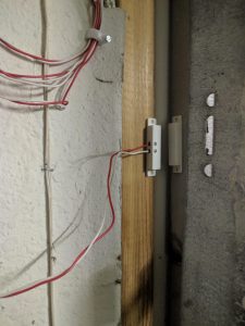
I cut some wire and attached it to the garage door terminals.


Then I attached the magnetic reed switch to the garage door and wired it up.

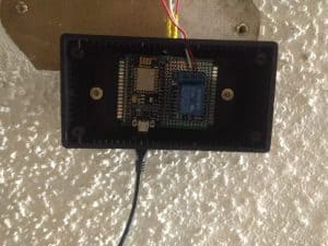
Finally, I moved the device into “production” by attaching the box to my ceiling by drilling through the box into a ceiling joist and wiring up everything to the box. (Excuse the gross popcorn ceiling in my garage, no idea why the previous owners decided to go with that…)

Automations
For our setup, we wanted to have two different automations now that our garage door was “smart”. First, we want to automatically close our garage door at 9 PM every night, then at 9:05 PM send a notification to my phone if the garage door is still open. This might be because something was in its way so it couldn’t close it automatically.
To do so, I added the following automation config to our Home Assistant configuration.
|
1 2 3 4 5 6 7 8 9 10 11 12 13 14 15 16 17 18 19 20 21 22 23 24 25 26 27 28 |
--- - alias: Close Garage Door trigger: - platform: time at: '21:00:00' condition: - condition: state entity_id: cover.garage_door state: 'open' action: - service: cover.close_cover entity_id: cover.garage_door - alias: Check if Garage Door Closed trigger: - platform: time at: '21:05:00' condition: - condition: state entity_id: cover.garage_door state: 'open' action: - service: notify.zack_pushbullet data: title: "Garage Door" message: "The garage door is open!" |
- The first automation runs at 9 PM every night, checks the garage door status and then calls the “close_cover” service if the door is open. Of course, the time here is flexible, you could even make it relative to the sunset!
- The second automation runs 5 minutes after the first and then sends a pushbullet notification to my phone if the garage door is still open. Feel free to plug in your favorite notification service here. Look out for a future post that goes over several notification platforms for Home Assistant.
Wrapping it Up
From this project you can see how useful and powerful the NodeMCU can be when running MicroPython. Turning your garage door into a smart garage door is a great project to get started into Home Automation. Some potential next steps are:
- Automatically open/close the garage door based on if anyone is home or arriving
- Turn on lights in the house when the garage door opens after sunset
- Allow you to respond to notifications, to tell Home Assistant to try closing the garage door again
- Add the reed switch to a manual garage door (I need to do this to my other garage door which doesn’t have an opener)
- As @SM2k pointed out on twitter, some garage door openers are considered “Security 2.0”, to accomplish the same thing you could hook up the relay to a garage controller like the 883LM. Read the conversation on twitter.
Let me know if you have any other good ideas in the comments!